SCPulley: Difference between revisions
No edit summary |
No edit summary |
||
| Line 172: | Line 172: | ||
''John: I have only run the new 42 teeth pulley briefly while doing a few engine test runs some weeks ago - no prop so I only ran the engine up to about 5000 rpm at 15% throttle opening, wastegate open. No problems - belt tracks OK & engine is very smooth after having crank pulley balanced. | ''John: I have only run the new 42 teeth pulley briefly while doing a few engine test runs some weeks ago - no prop so I only ran the engine up to about 5000 rpm at 15% throttle opening, wastegate open. No problems - belt tracks OK & engine is very smooth after having crank pulley balanced.'' | ||
I'm sure that the slightly smaller diameter 40 teeth pulley will be OK for our application - at maximum prop rpm it has the same 5% overspeed as the previous Gen 2 PSRU/ existing 36 teeth pulley combination, and it might not require the other modifications to the SC bracket & tension rod that I had to do for the larger pulley. | ''I'm sure that the slightly smaller diameter 40 teeth pulley will be OK for our application - at maximum prop rpm it has the same 5% overspeed as the previous Gen 2 PSRU/ existing 36 teeth pulley combination, and it might not require the other modifications to the SC bracket & tension rod that I had to do for the larger pulley.'' | ||
'' | |||
---- | ---- | ||
| Line 187: | Line 186: | ||
Fenner tells me their tolerance is +- 0.08mm or 0.003", so I am not within their tolerance | Fenner tells me their tolerance is +- 0.08mm or 0.003", so I am not within their tolerance | ||
Is that what you meant by stacking the tolerances on the minus side - if the shaft is too small, then making the pulley on the small side will still let it work OK? | |||
Your shaft actually measured the full 20mm - 0.7874"? | |||
I am waiting now for a call-back from Fenner to see what they recommend on a shaft I am measuring at 0.7795 or maybe 0.780 at best | |||
I suppose i can try re-measuring with another micrometer, but I am currently using Mattoon digital callipers with .0005 supposed accuracy. | I suppose i can try re-measuring with another micrometer, but I am currently using Mattoon digital callipers with .0005 supposed accuracy. | ||
''John: I have been thinking about the SC pulley & shaft during the day.'' | |||
I | ''It is about 12 months since I replaced the pulley & the details are becoming harder to remember.'' | ||
''I measured the shaft in a few different positions & angles - the shaft was +0/ -0.005 as I have previously advised - on average I think'' | |||
''It was just on or within tolerance for the Fenner bushing.'' | |||
was that the bushing had a factor of safety of about 10 on the load our application would apply. If it was close to the bushing load limit | ''I bought the bushing and did some experiments using a hose clamp adjusted to 45mm to serve as the pulley. When I tightened the bushing it locked on to the shaft - provided the pulley bore was within tolerance. it took a bit of experimenting to convince myself that the bushing would work OK - but I also loaded the pulley bore tolerance on the minus side. Another contributing factor to my decision was that the bushing had a factor of safety of about 10 on the load our application would apply. If it was close to the bushing load limit I may not have used it.'' | ||
I may not have used it. | |||
In any event, I ordered the pulley & installed it - the recommended torque is 170 ft-lbs which I couldn't physically achieve (got about 150 ft-lbs) so I think it | ''In any event, I ordered the pulley & installed it - the recommended torque is 170 ft-lbs which I couldn't physically achieve (got about 150 ft-lbs) so I think it is pretty well locked-on. However, the engine has only been run for short durations & under virtually no load so the bushing is still unproven.'' | ||
is pretty well locked-on. However, the engine has only been run for short durations & under virtually no load so the bushing is still unproven. | |||
My suggestions are as follows: | ''My suggestions are as follows'': | ||
''1) Take multiple shaft dia measurements and see how they average out'' | |||
a keyway or longer grip than was available | ''2) See what Fenner say & if they can recommend another bushing if this type is out of tolerance - I found that most of the bushings required either a keyway or longer grip than was available'' | ||
3) The other option is to go for an interference fit pulley. If you look at http://pulleyboys.com/swap.html you will see that they install the pulley using the internally threaded end of the SC shaft to pull on the new pulley - maybe they are worth talking to to find out the correct pulley bore size for the interference fit. I recall that their type of pulley puller/ pusher was typical of those available following a web search. It would be very difficult to press fit the pulley if the SC was dismantled as the pulley obstructs access to the snout bolts. | ''3) The other option is to go for an interference fit pulley. If you look at http://pulleyboys.com/swap.html you will see that they install the pulley using the internally threaded end of the SC shaft to pull on the new pulley - maybe they are worth talking to to find out the correct pulley bore size for the interference fit. I recall that their type of pulley puller/ pusher was typical of those available following a web search. It would be very difficult to press fit the pulley if the SC was dismantled as the pulley obstructs access to the snout bolts.'' | ||
If I can think of anything else I will email. | ''If I can think of anything else I will email.'' | ||
FWIW this firm seem to be experts in SC rebuilding etc http://www.thehighspeedlab.com/supercharger_rebuild_svcs.html | ''FWIW this firm seem to be experts in SC rebuilding etc [http://www.thehighspeedlab.com/supercharger_rebuild_svcs.html|http://www.thehighspeedlab.com/supercharger_rebuild_svcs.html]'' | ||
'' | |||
''John: From memory, my SC shaft measured 0.782 in so it was just outside the Fenner tolerance of -.003 in. Hence my adjusting the replacement pulley bore tolerance to the minus limit. The bushing torqued up OK and I am satisfied of its adequacy. However, your SC shaft is well outside the tolerance and I wouldn't be comfortable about using the bushing without Fenner's approval. | ''John: From memory, my SC shaft measured 0.782 in so it was just outside the Fenner tolerance of -.003 in. Hence my adjusting the replacement pulley bore tolerance to the minus limit. The bushing torqued up OK and I am satisfied of its adequacy. However, your SC shaft is well outside the tolerance and I wouldn't be comfortable about using the bushing without Fenner's approval.'' | ||
Let me know what they say - I can take off the pulley & check the shaft dia & bore.'' | ''Let me know what they say - I can take off the pulley & check the shaft dia & bore.'' | ||
---- | ---- | ||
| Line 254: | Line 235: | ||
''John: I think it was just personal preference - my belt tracks in the middle of the 50 mm wide teeth - other than breaking, | ''John: I think it was just personal preference - my belt tracks in the middle of the 50 mm wide teeth - other than breaking, there is no way the belt can ever contact the fence. The larger diameter fence may have also obstructed access to the oil fill plug.'' | ||
there is no way the belt can ever contact the fence. The larger diameter fence may have also obstructed access to the | |||
oil fill plug. | |||
I remade the SC tension rod into a proper turnbuckle with left & right hand threaded rod ends & lock nuts rather than the piece of junk supplied by Egg. I also bought a couple of cheap belt tension gauges (50-150 lbs, 100-300 lbs) from McMaster-Carr. The tension rod can be screwed out by hand about 1 in, enough to take all the belt slap with a belt tension of about 80-100 lbs - very low for this type of belt. I wouldn't run the SC without it now & strongly recommend replacing the Egg rod with a much better arrangement.'' | ''I remade the SC tension rod into a proper turnbuckle with left & right hand threaded rod ends & lock nuts rather than the piece of junk supplied by Egg. I also bought a couple of cheap belt tension gauges (50-150 lbs, 100-300 lbs) from McMaster-Carr. The tension rod can be screwed out by hand about 1 in, enough to take all the belt slap with a belt tension of about 80-100 lbs - very low for this type of belt. I wouldn't run the SC without it now & strongly recommend replacing the Egg rod with a much better arrangement.'' | ||
| Line 267: | Line 246: | ||
Brian: I got my Fenner bushing. It does seem a bit loose, but maybe that's just because I don't yet have anything to put over it to keep it from expanding. | Brian: I got my Fenner bushing. It does seem a bit loose, but maybe that's just because I don't yet have anything to put over it to keep it from expanding. | ||
''John: I had the same feeling :) | ''John: I had the same feeling :)'' | ||
'' | |||
Brian: I am going to order the pulley tomorrow. If it's still doesn't seem tight enough with the pulley on it, i will add shim stock between the SC shaft and the bushing. | Brian: I am going to order the pulley tomorrow. If it's still doesn't seem tight enough with the pulley on it, i will add shim stock between the SC shaft and the bushing. | ||
| Line 290: | Line 268: | ||
Brian: You specified 45mm ID +0 -0.15 - i wondered why you specified -0.15 instead of -0.08 (to match the Fenner bushing minimum tolerance). Was 0.15 the best tolerance they could do? Or were you just ok with them going smaller than 44.92mm, possibly down to 44.85mm? Do you know exactly what you ended up with? | Brian: You specified 45mm ID +0 -0.15 - i wondered why you specified -0.15 instead of -0.08 (to match the Fenner bushing minimum tolerance). Was 0.15 the best tolerance they could do? Or were you just ok with them going smaller than 44.92mm, possibly down to 44.85mm? Do you know exactly what you ended up with? | ||
''John: For some unknown reason I think I doubled up on the Fenner tolerance - maybe I thought that the +/-.008 say .015 spread was a reasonable fabrication tolerance to avoid additional cost from specifying an unusually tight tolerance. | ''John: For some unknown reason I think I doubled up on the Fenner tolerance - maybe I thought that the +/-.008 say .015 spread was a reasonable fabrication tolerance to avoid additional cost from specifying an unusually tight tolerance. I vaguely recall that the pulley was supplied with a bore of 45mm +0/-.005. It certainly wasn't near the minus limit. I didn't know what they could produce so I guessed that a minus tolerance was more likely to fit the bushing/shaft combination than just using the standard 45 +/-.008. '' | ||
I vaguely recall that the pulley was supplied with a bore of 45mm +0/-.005. It certainly wasn't near the minus limit. I didn't know what they could produce so I guessed that a minus tolerance was more likely to fit the bushing/shaft combination than just using the standard 45 +/-.008. | |||
'' | |||
Brian: Do you recall if they told you what tolerances they could provide on this part? I was thinking of specifying the bore at 44.92 plus 0, minus (whatever their min tolerance is) to help deal with the smaller-than-spec SC output shaft. | Brian: Do you recall if they told you what tolerances they could provide on this part? I was thinking of specifying the bore at 44.92 plus 0, minus (whatever their min tolerance is) to help deal with the smaller-than-spec SC output shaft. | ||
''John: Probably worthwhile to run with the tighter tolerance - best to ask the fabricator what they can do. You have to remember that I was dealing through Gates & couldn't talk to the fabricator so I made a lot of guesses. | ''John: Probably worthwhile to run with the tighter tolerance - best to ask the fabricator what they can do. You have to remember that I was dealing through Gates & couldn't talk to the fabricator so I made a lot of guesses.'' | ||
I previously mentioned that I couldn't torque the bushing up to the specified 170 ft-lbs ( I think) - I have wondered whether this was because of the tighter fit of the the pulley bore to bushing from the minus tolerance.'' | ''I previously mentioned that I couldn't torque the bushing up to the specified 170 ft-lbs ( I think) - I have wondered whether this was because of the tighter fit of the the pulley bore to bushing from the minus tolerance.'' | ||
| Line 336: | Line 311: | ||
Brian: Sorry for all the questions - i just want to make sure I spec this exactly right when i order it | Brian: Sorry for all the questions - i just want to make sure I spec this exactly right when i order it | ||
''John: No problem - please make sure to specify the surface finish as "black hardcoat" rather than anodised. I understand that hardcoating is a special chromic anodising process that hardens as well as colours the surface. | ''John: No problem - please make sure to specify the surface finish as "black hardcoat" rather than anodised. I understand that hardcoating is a special chromic anodising process that hardens as well as colours the surface.'' | ||
''I did not know what grade of aluminium would be used so I assumed 6061 in calculating the minimum hub thickness for the Trantorque bushing. It might pay to check with the fabricator what they would use (in the absence of a more specific type of aluminium)'' | |||
---- | |||
Brian: Funny you mentioned in the last paragraph about the strength of the aluminium. Using "Brian's Seat of Pants" engineering, I looked at the drawing and thought about the forces from the bushing pushing out, and decided to bump up the hub OD a bit - probably 80mm. | |||
I just have one question left over from going over all this last night. | |||
There are 2 lines, which i took to mean the top & bottom of the teeth. But that threw me because the outer line is marked 105.58mm and the notes say pitch diameter (which i take to mean OD of the teeth) is 106.95mm, which would mean that the outer line is the bottom (inner) part of the teeth, leaving me to wonder what the inner line is | |||
If the blue line is the bottom of the teeth and perhaps the teeth are shown in the little box with the V above that, then what is the red line? | |||
[[File:SCPulley7.jpg|200px|Modified Pulley Sketch]] | |||
''John: The pitch diameter is a theoretical line running in the continuous part of the belt i.e. it is above the teeth. For our belt this is 106.95 mm/ 4.211 in'' | |||
''The top of teeth dia (pulley OD) is 105.58 mm/ 4.157 in - the blue line in the sketch. The pink line is the bottom of the teeth.'' | |||
''These are standard dimensions set by the no. of teeth, belt pitch & tooth type. The pulley should be supplied stamped P42-8MGT-85 shorthand for 42 teeth, 8M belt pitch, GT tooth profile, 85mm wide pulley. Only deviation is the fence dia I specified (115mm) is less than the standard 125 mm.'' | |||
''When I started investigating this belt & pulley business, I was surprised that all the critical dimensions were referenced to an imaginary line! '' | |||
''I doubt that the hub thickness needs to be thickened - easy to check using the methodology shown in the Trantorque bushing brochure. The bushing & pulley are much heavier than the original.'' | |||
I | ''I keep on reminding myself that the major benefit of all this screwing around with the engine & accessories will be a vastly better understanding of how it was assembled & is supposed to work.'' | ||
Revision as of 03:43, 6 December 2009
Super Charger Pulley Replacement
John Moody
I saw your comments regarding the supercharger pulley replacement. No need to reinvent the wheel. I did all that a couple of years ago including redesigning the pulley & sourcing a fabricator.
I changed the pulley from a 36 teeth unit to 42 teeth (about 4.2 in dia) - this change reduces the drive ratio to 108/42 = 2.57 & the maximum SC speed to 14000 rpm @ 5450 engine rpm ( 2700 prop rpm) for the G3 PSRU
I assume that the SOHC H4's use the same 108 teeth drive pulley as the STi's.
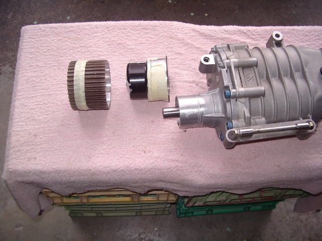
Below are a series of photos I took during the removal/ replacement process:
1. The existing pulley is 2 pieces. A thick aluminium "bell" press fit onto the SC shaft with a thin "teeth ring"
pressed on to the bell. I didn't have any prior knowledge of what was there before I started cutting it off so I did it the hard way.
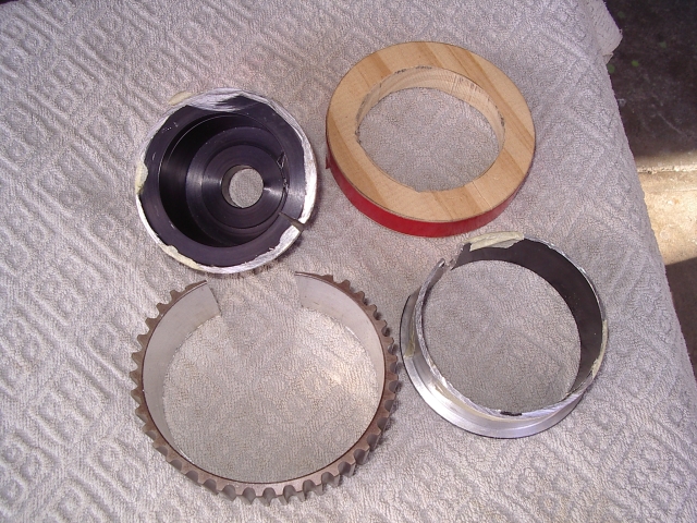
First step is to cut off the teeth ring - it is only about 3/32 in thick & the bell lip below is about 1/16 thick so go easy with the dremel. See details in the second photo.
Second step is to cut-off the bell without nicking the shaft. The bell/ shaft overlap is 1 in. I used a series of parallel cut to get down near the shaft. I then cut-off the thin part of the bell & used a cheap gear puller to pull off the bell.
I think Brian Meyette went straight to the gear puller & it worked OK.
The SC shaft is 20 mm dia (0.787in +/-)
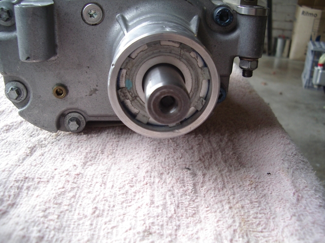
2. SC shaft details. The pilot hole in the shaft had a square wedge driven into it to prevent the standard pulley pullers from working. The SC oil fill plug is the brass plug on the LHS bottom.
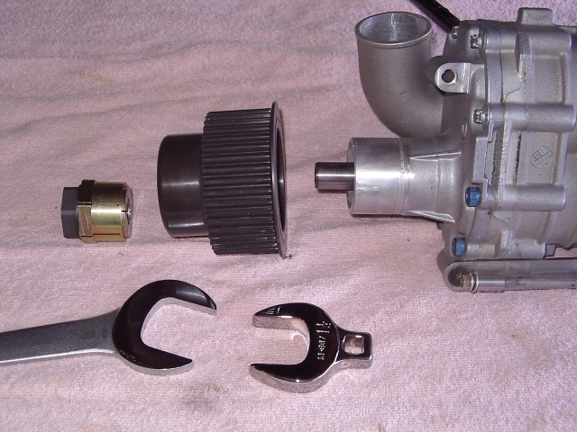
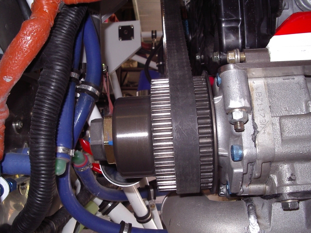
3. The new SC pulley is shown below. I had the teeth made a bit narrower as I had measured the tracking position of
the belt. The gold/ black thing on the LHS is a Fenner Trantorque bushing I used to fix the pulley on the shaft.
It is an expanding bushing that locks the both the pulley & shaft. 45mm od/ 20mm id. The factor of safety on the
bushing toque vs. SC pulley torque is about 10. The bushing uses 1-1/2 & 1-1/4 in wrenches to tighten up & is torqued to about 300 in-lbs from memory.
4. Pulley installed. The existing belt is reused & consequently, the SC mount bracket has to be shortened by about 0.4 in. I also replaced the SC tension rod with a proper turnbuckle arrangement so that the belt could be properly tensioned to remove most of the "belt slap" evident using Eggs SC rod. I also bout a $20 belt tension tester from McMaster-Carr so I could properly set the tension in future.
Replacement pulley & bushing details:
1)Replacement pulley design. I settled for the 50mm wide teeth. Mine works OK - depends where your belt tracks. I didn't allow for any misalignment due from modifying the SC bracket so the safest course would be to get the 65mm wide teeth.
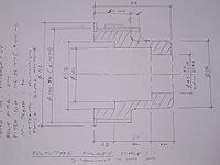
2) The sketch provides the relevant details of the replacement pulley. You need to finalise how wide you want the teeth & redraw the sketch. I would change the finish from "black anodise" to "hardcoat" - it may be the same but hardcoat is preferred if it is not.
3) I am not a mechanical engineer & haven't optimised the design. The pulley is quite heavy & I am sure that the wall thickness of the bell could be substantially reduced to reduce weight.
4) A critical dimension is the specified pulley bore - I think the sketch has "45mm +0/ -0.15mm" This dimension is to suit the keyless bushing which has tight tolerances on the shaft & bore diameters.
5) Details of the bushing are in this file File:Ttqtech.pdf.
The SC shaft is 20mm (0.787 in) so the required
bushing p/n is 6202811. My SC shaft was 0.787 +0/ -.005 in so I put all the bore tolerance on the
minus side to match the shaft. Seems to have worked as the bushing torqued up OK. I used this
bushing because I didn't want to disassemble the SC to press-fit the new pulley (also didn't
know how to design for a press-fit) The bushing is also fairly heavy - 1 lb or so from memory.
6) You should measure the shaft diameter & check its tolerance.
7) I bought the bushing from Motion Industries locally, but McMaster-Carr appear to have it
p/n 2298k19 $60.98 (2007). You will also need a thin 1-3/4 wrench and a 1-1/2 wrench or socket
to tighten it.
8) The pulley fabricator was Motion Systems in MI. Brian Meyette found them very helpful to deal with. I don't know whether they know or care that the parts were for aircraft but I wouldn't mention it.
Contact details are:
Motion Systems Inc.
21335 Schoenherr
Warren MI 48089
ph 586-774-5666
fax 586-774-5768
Contact is William Ericson (Bill@motion-pulleys.com)
Apparently he was very helpful to Brian & he sent the quote very quickly. Their order/ job number for my pulley was 16358.
I think they charged about $175 with volume discounts starting at 5 units.
9) I had to shorten my SC mount bracket by about 0.4 in to accommmodate the existing belt.
10) SC tension rod parts. I bought the parts from ChassisShop www.chassisshop.com - same place I bought the big NACA duct for the intercooler inlet.
Parts were:
Tube Adapters - 5/16-24 LH thread for 5/8OD x 058 tube p/n C73-819-2, RH thread C73-818-2 $10.04 each for packs of 2
They also have chrome-moly tube 5/8 x 058 p/n 41-58-058 $2.64/ft - 2ft reqd
Rod ends LH 5/16 p/n CB-5 $5.94, RH CM-5 $5.74
Jam nuts - already had some - pkg 6 LH C73-055 $5.20, RH C73-054 $3.70
Other than the jam nuts, I bought all the parts required - more convenient than another order to ACS.
I also bought a pack(2) of safety washers p/n C73-463-2 $5.50 - these allow greater angular misalignment of the rod end handy - particularly for the rod connection under the SC.
Ask for a catalog with the order.
Hope this makes sense - if there is anything I can do to help please ask
John
Questions
Brian: I’m getting to the point of getting ready to do something about my supercharger pulley. I know there was some talk of people doing it, then it died out. I think Randy was going to do it, but then he decided to go turbocharged.
Has anyone besides John Moody swapped out their SC pulley? Do any of you plan to?
How’s your pulley working out so far, John? Best to go with the number of teeth you decided on, or the slightly larger one Randy was proposing?
John: I have only run the new 42 teeth pulley briefly while doing a few engine test runs some weeks ago - no prop so I only ran the engine up to about 5000 rpm at 15% throttle opening, wastegate open. No problems - belt tracks OK & engine is very smooth after having crank pulley balanced.
I'm sure that the slightly smaller diameter 40 teeth pulley will be OK for our application - at maximum prop rpm it has the same 5% overspeed as the previous Gen 2 PSRU/ existing 36 teeth pulley combination, and it might not require the other modifications to the SC bracket & tension rod that I had to do for the larger pulley.
Brian: I was about to order the Fenner bushing, but ran into a snag & wanted to let you know about it. It seems the Fenner bushing's tolerances will not work with my shaft, and i wonder if it's within tolerances with your shaft.
I measured my shaft at 0.7795" which is 19.7993mm
Fenner tells me their tolerance is +- 0.08mm or 0.003", so I am not within their tolerance
Is that what you meant by stacking the tolerances on the minus side - if the shaft is too small, then making the pulley on the small side will still let it work OK?
Your shaft actually measured the full 20mm - 0.7874"?
I am waiting now for a call-back from Fenner to see what they recommend on a shaft I am measuring at 0.7795 or maybe 0.780 at best
I suppose i can try re-measuring with another micrometer, but I am currently using Mattoon digital callipers with .0005 supposed accuracy.
John: I have been thinking about the SC pulley & shaft during the day.
It is about 12 months since I replaced the pulley & the details are becoming harder to remember.
I measured the shaft in a few different positions & angles - the shaft was +0/ -0.005 as I have previously advised - on average I think
It was just on or within tolerance for the Fenner bushing.
I bought the bushing and did some experiments using a hose clamp adjusted to 45mm to serve as the pulley. When I tightened the bushing it locked on to the shaft - provided the pulley bore was within tolerance. it took a bit of experimenting to convince myself that the bushing would work OK - but I also loaded the pulley bore tolerance on the minus side. Another contributing factor to my decision was that the bushing had a factor of safety of about 10 on the load our application would apply. If it was close to the bushing load limit I may not have used it.
In any event, I ordered the pulley & installed it - the recommended torque is 170 ft-lbs which I couldn't physically achieve (got about 150 ft-lbs) so I think it is pretty well locked-on. However, the engine has only been run for short durations & under virtually no load so the bushing is still unproven.
My suggestions are as follows:
1) Take multiple shaft dia measurements and see how they average out
2) See what Fenner say & if they can recommend another bushing if this type is out of tolerance - I found that most of the bushings required either a keyway or longer grip than was available
3) The other option is to go for an interference fit pulley. If you look at http://pulleyboys.com/swap.html you will see that they install the pulley using the internally threaded end of the SC shaft to pull on the new pulley - maybe they are worth talking to to find out the correct pulley bore size for the interference fit. I recall that their type of pulley puller/ pusher was typical of those available following a web search. It would be very difficult to press fit the pulley if the SC was dismantled as the pulley obstructs access to the snout bolts.
If I can think of anything else I will email.
FWIW this firm seem to be experts in SC rebuilding etc [1]
John: From memory, my SC shaft measured 0.782 in so it was just outside the Fenner tolerance of -.003 in. Hence my adjusting the replacement pulley bore tolerance to the minus limit. The bushing torqued up OK and I am satisfied of its adequacy. However, your SC shaft is well outside the tolerance and I wouldn't be comfortable about using the bushing without Fenner's approval.
Let me know what they say - I can take off the pulley & check the shaft dia & bore.
Brian: Thanks for all the info. What prompted you to change the fence diameter from 125 to 115mm?
John: I think it was just personal preference - my belt tracks in the middle of the 50 mm wide teeth - other than breaking, there is no way the belt can ever contact the fence. The larger diameter fence may have also obstructed access to the oil fill plug.
I remade the SC tension rod into a proper turnbuckle with left & right hand threaded rod ends & lock nuts rather than the piece of junk supplied by Egg. I also bought a couple of cheap belt tension gauges (50-150 lbs, 100-300 lbs) from McMaster-Carr. The tension rod can be screwed out by hand about 1 in, enough to take all the belt slap with a belt tension of about 80-100 lbs - very low for this type of belt. I wouldn't run the SC without it now & strongly recommend replacing the Egg rod with a much better arrangement.
Brian: I got my Fenner bushing. It does seem a bit loose, but maybe that's just because I don't yet have anything to put over it to keep it from expanding.
John: I had the same feeling :)
Brian: I am going to order the pulley tomorrow. If it's still doesn't seem tight enough with the pulley on it, i will add shim stock between the SC shaft and the bushing.
I have several questions about the drawing. It's a bit hard to read, and I am not clear on a couple things about it. Is this the actual drawing you sent to Gates & they made the pulley from?
John: Basically yes - I may have cleaned it up a bit to make it clearer -but all the info I wanted to specify is there. I would go direct to the fabricator. The price from Gates was double the fabricators price. For $175 or whatever price they quoted direct to Randy, it is hardly worth going beyond the company that fabricated my pulley
Brian: You didn't specify any radius for the places where a radius is shown - they were ok with that?
John: Yes - I didn't get any questions from the fabricator about anything
Brian: You didn't specify a width for the inboard fence - they were ok with that?
John: Yes - I assumed (correctly?) that they would have a standard detail for it
Brian: You specified 45mm ID +0 -0.15 - i wondered why you specified -0.15 instead of -0.08 (to match the Fenner bushing minimum tolerance). Was 0.15 the best tolerance they could do? Or were you just ok with them going smaller than 44.92mm, possibly down to 44.85mm? Do you know exactly what you ended up with?
John: For some unknown reason I think I doubled up on the Fenner tolerance - maybe I thought that the +/-.008 say .015 spread was a reasonable fabrication tolerance to avoid additional cost from specifying an unusually tight tolerance. I vaguely recall that the pulley was supplied with a bore of 45mm +0/-.005. It certainly wasn't near the minus limit. I didn't know what they could produce so I guessed that a minus tolerance was more likely to fit the bushing/shaft combination than just using the standard 45 +/-.008.
Brian: Do you recall if they told you what tolerances they could provide on this part? I was thinking of specifying the bore at 44.92 plus 0, minus (whatever their min tolerance is) to help deal with the smaller-than-spec SC output shaft.
John: Probably worthwhile to run with the tighter tolerance - best to ask the fabricator what they can do. You have to remember that I was dealing through Gates & couldn't talk to the fabricator so I made a lot of guesses.
I previously mentioned that I couldn't torque the bushing up to the specified 170 ft-lbs ( I think) - I have wondered whether this was because of the tighter fit of the the pulley bore to bushing from the minus tolerance.
Brian: I can't read the numbers at the bottom - the left-most one looks like maybe a 23 that was changed to a 28?
The 42 seems to have been changed to a 37 - correct?
John: Correct - I must have decided to increase the clearance between the pulley & the SC snout - the numbers across the bottom should read 28, 37 & 20 adding up to 85
Brian: The inner step (from 60mm to 76mm ID) is necessary to clear the SC housing?
John: Correct - you could probably make it a lot thinner & save weight if you knew how to design these things & properly calculate what was required.
Brian: Can you tell me what the pitch diameter is that you used? I can't read it well - it looks like 106.95mm - is this correct? Is that the inch quivalent in parenthesis beside it? Does it say 4.211"?
John: The pitch diameter (from the Gates Design Manual) is 106.95 mm (4.211 in), fence OD is 115mm,
Brian: What is the belt pitch? Is that saying 8mm?
John: It should be belt pitch 8mm - I think I used the Gates designator 8M. Tooth type should be Gates Powergrip GT2
Brian: The teeth width spec says 50 NTS - what does NTS mean?
John: NTS - not to scale - I had a last minute rethink & increased the tooth width from 40 to 50mm, You might want to make it 65mm to match the old pulley - depends where your belt tracks relative to the width of the teeth
Brian: And last - at the bottom, it says "dimensions in mm". What is the word after that? Looks like UNO or UND - not sure if it's important or not.
John: UNO - unless noted otherwise - sorry - I used to be be a structural engineer so you tend to fall back to old drawing-office shorthand when preparing sketches
Brian: Sorry for all the questions - i just want to make sure I spec this exactly right when i order it
John: No problem - please make sure to specify the surface finish as "black hardcoat" rather than anodised. I understand that hardcoating is a special chromic anodising process that hardens as well as colours the surface.
I did not know what grade of aluminium would be used so I assumed 6061 in calculating the minimum hub thickness for the Trantorque bushing. It might pay to check with the fabricator what they would use (in the absence of a more specific type of aluminium)
Brian: Funny you mentioned in the last paragraph about the strength of the aluminium. Using "Brian's Seat of Pants" engineering, I looked at the drawing and thought about the forces from the bushing pushing out, and decided to bump up the hub OD a bit - probably 80mm.
I just have one question left over from going over all this last night.
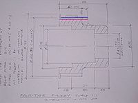
There are 2 lines, which i took to mean the top & bottom of the teeth. But that threw me because the outer line is marked 105.58mm and the notes say pitch diameter (which i take to mean OD of the teeth) is 106.95mm, which would mean that the outer line is the bottom (inner) part of the teeth, leaving me to wonder what the inner line is
If the blue line is the bottom of the teeth and perhaps the teeth are shown in the little box with the V above that, then what is the red line?
John: The pitch diameter is a theoretical line running in the continuous part of the belt i.e. it is above the teeth. For our belt this is 106.95 mm/ 4.211 in
The top of teeth dia (pulley OD) is 105.58 mm/ 4.157 in - the blue line in the sketch. The pink line is the bottom of the teeth.
These are standard dimensions set by the no. of teeth, belt pitch & tooth type. The pulley should be supplied stamped P42-8MGT-85 shorthand for 42 teeth, 8M belt pitch, GT tooth profile, 85mm wide pulley. Only deviation is the fence dia I specified (115mm) is less than the standard 125 mm.
When I started investigating this belt & pulley business, I was surprised that all the critical dimensions were referenced to an imaginary line!
I doubt that the hub thickness needs to be thickened - easy to check using the methodology shown in the Trantorque bushing brochure. The bushing & pulley are much heavier than the original.
I keep on reminding myself that the major benefit of all this screwing around with the engine & accessories will be a vastly better understanding of how it was assembled & is supposed to work.
