SCPulley: Difference between revisions
No edit summary |
No edit summary |
||
| Line 72: | Line 72: | ||
Replacement pulley & bushing details: | Replacement pulley & bushing details: | ||
[[File:SCPulley6.jpg|200px|thumb|left|alt text]] | |||
[[File:ttqtech.pdf]] | [[File:ttqtech.pdf|Trantorque Keyless Bushings Information]] | ||
Revision as of 03:10, 6 December 2009
Super Charger Pulley Replacement
John Moody
I saw your comments regarding the supercharger pulley replacement. No need to reinvent the wheel. I did all that a couple of years ago including redesigning the pulley & sourcing a fabricator.
I changed the pulley from a 36 teeth unit to 42 teeth (about 4.2 in dia) - this change reduces the drive ratio to 108/42 = 2.57 & the maximum SC speed to 14000 rpm @ 5450 engine rpm ( 2700 prop rpm) for the G3 PSRU
I assume that the SOHC H4's use the same 108 teeth drive pulley as the STi's.
Below are a series of photos I took during the removal/ replacement process:
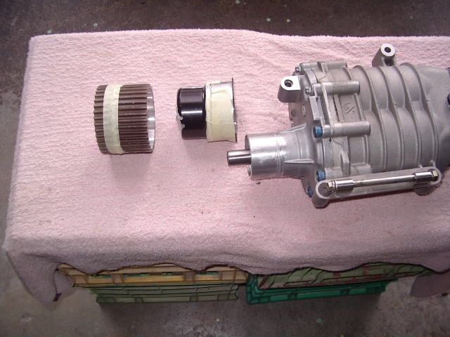
1. The existing pulley is 2 pieces. A thick aluminium "bell" press fit onto the SC shaft with a thin "teeth ring"
pressed on to the bell. I didn't have any prior knowledge of what was there before I started cutting it off so I did it the hard way.
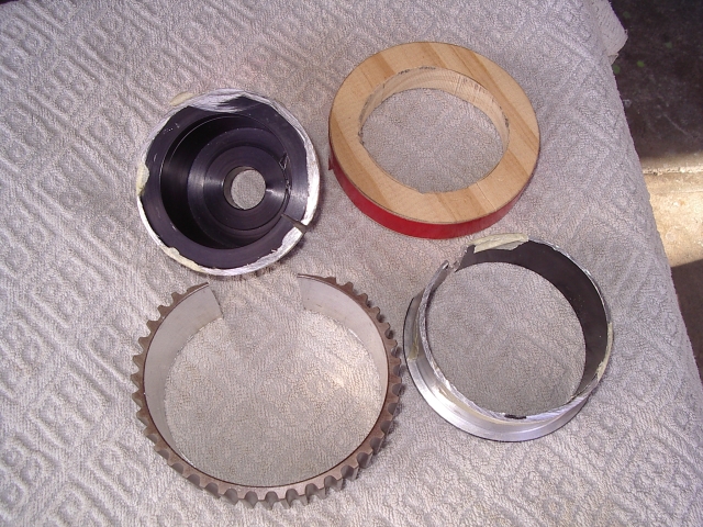
First step is to cut off the teeth ring - it is only about 3/32 in thick & the bell lip below is about 1/16 thick so go easy
with the dremel. See details in the second photo.
Second step is to cut-off the bell without nicking the shaft. The bell/ shaft overlap is 1 in. I used a series of parallel
cut to get down near the shaft. I then cut-off the thin part of the bell & used a cheap gear puller to pull off the bell.
I think Brian Meyette went straight to the gear puller & it worked OK.
The SC shaft is 20 mm dia (0.787in +/-)
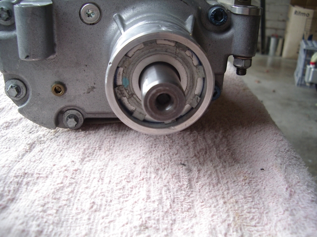
2. SC shaft details. The pilot hole in the shaft had a square wedge driven into it to prevent the standard pulley pullers
from working. The SC oil fill plug is the brass plug on the LHS bottom.
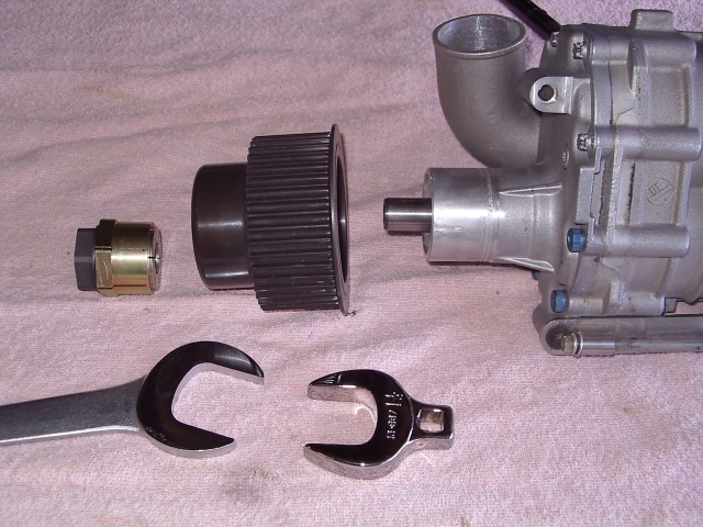
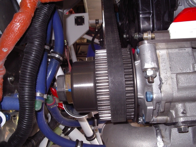
3. The new SC pulley is shown below. I had the teeth made a bit narrower as I had measured the tracking position of
the belt. The gold/ black thing on the LHS is a Fenner Trantorque bushing I used to fix the pulley on the shaft.
It is an expanding bushing that locks the both the pulley & shaft. 45mm od/ 20mm id. The factor of safety on the
bushing toque vs. SC pulley torque is about 10. The bushing uses 1-1/2 & 1-1/4 in wrenches to tighten up & is torqued to
about 300 in-lbs from memory.
4. Pulley installed. The existing belt is reused & consequently, the SC mount bracket has to be shortened by about 0.4
in. I also replaced the SC tension rod with a proper turnbuckle arrangement so that the belt could be properly tensioned
to remove most of the "belt slap" evident using Eggs SC rod. I also bout a $20 belt tension tester from McMaster-
Carr so I could properly set the tension in future.
Replacement pulley & bushing details:
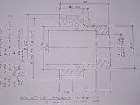
1)Replacement pulley design. I settled for the 50mm wide teeth.
Mine works OK - depends where your belt tracks. I didn't allow for any misalignment due from modifying the SC bracket
so the safest course would be to get the 65mm wide teeth.
2) The sketch provides the relevant details of the replacement pulley.
You need to finalise how wide you want the teeth & redraw the sketch. I would change the finish from
"black anodise" to "hardcoat" - it may be the same but hardcoat is preferred if it is not.
3) I am not a mechanical engineer & haven't optimised the design. The pulley is quite heavy & I
am sure that the wall thickness of the bell could be substantially reduced to reduce weight.
4) A critical dimension is the specified pulley bore - I think the sketch has "45mm +0/ -0.15mm"
This dimension is to suit the keyless bushing which has tight tolerances on the shaft & bore diameters.
5) Details of the bushing are in the attached file. The SC shaft is 20mm (0.787 in) so the required
bushing p/n is 6202811. My SC shaft was 0.787 +0/ -.005 in so I put all the bore tolerance on the
minus side to match the shaft. Seems to have worked as the bushing torqued up OK. I used this
bushing because I didn't want to disassemble the SC to press-fit the new pulley (also didn't
know how to design for a press-fit) The bushing is also fairly heavy - 1 lb or so from memory.
6) You should measure the shaft diameter & check its tolerance.
7) I bought the bushing from Motion Industries locally, but McMaster-Carr appear to have it
p/n 2298k19 $60.98 (2007). You will also need a thin 1-3/4 wrench and a 1-1/2 wrench or socket
to tighten it.
8) The pulley fabricator was Motion Systems in MI. Brian Meyette found them very helpful to deal with.
I don't know whether they know or care that the parts were for aircraft but I wouldn't mention it.
Contact details are:
Motion Systems Inc.
21335 Schoenherr
Warren MI 48089
ph 586-774-5666
fax 586-774-5768
Contact is William Ericson (Bill@motion-pulleys.com)
Apparently he was very helpful to Brian & he sent the quote very quickly.
Their order/ job number for my pulley was 16358.
I think they charged about $175 with volume discounts starting at 5 units.
9) I had to shorten my SC mount bracket by about 0.4 in to accommmodate the existing belt.
10) SC tension rod parts. I bought the parts from ChassisShop www.chassisshop.com - same place I bought the big NACA duct for the intercooler
inlet.
Parts were:
Tube Adapters - 5/16-24 LH thread for 5/8OD x 058 tube p/n C73-819-2, RH thread C73-818-2 $10.04 each for packs of 2
They also have chrome-moly tube 5/8 x 058 p/n 41-58-058 $2.64/ft - 2ft reqd
Rod ends LH 5/16 p/n CB-5 $5.94, RH CM-5 $5.74
Jam nuts - already had some - pkg 6 LH C73-055 $5.20, RH C73-054 $3.70
Other than the jam nuts, I bought all the parts required - more convenient than another order to ACS.
I also bought a pack(2) of safety washers p/n C73-463-2 $5.50 - these allow greater angular misalignment of the rod end
handy - particularly for the rod connection under the SC.
Ask for a catalog with the order.
Hope this makes sense - if there is anything I can do to help please ask
John
